| Service Hotline: | 0755-25566186 |
| 130-6691-6396 |
| Service Hotline: | 0755-25566186 |
| 130-6691-6396 |

Shenzhen Juke Industry Co., Ltd.
Tel: (86) 755-25566186
Fax: (86) 755-29668058
E-mail:jakizhu@163.com
Contact:
Zhu Wenwu
Mobile: 13928444330
QQ: 504060299
Zhu Ganghui
Mobile: 13714798680
QQ: 1046243838
Miss Zhou
Mobile: 13066916396
QQ: 1253838927
Address:1006 Huamei Building, Huamei Road, Songgang, Bao'an District. Shenzhen
One, arch type
The component feeder and the substrate (PCB) are fixed, and the patch head (with multiple vacuum suction nozzles) moves back and forth between the feeder and the substrate, removes the components from the feeder, adjusts the position and orientation of the components, and then Place on the substrate. Since the patch head is mounted on an arched X/Y coordinate moving beam, it is named.
Arrangement of the position and direction of components of the arch mounter :
1), mechanical adjustment center position, suction nozzle rotation adjustment direction, this method can achieve limited accuracy, later models have no longer used.
2), laser recognition, X/Y coordinate system adjustment position, suction nozzle rotation adjustment direction, this method can realize the identification in the flight process, but can not be used for ball grid array components BGA.
3) Camera identification, X/Y coordinate system adjustment position, suction nozzle rotation adjustment direction, general camera fixation, patch head flying across the camera, image recognition, a bit less time than laser recognition, but any component can be identified, but also Camera recognition systems that realize recognition during flight have other sacrifices in the mechanical structure.
This form is limited in speed due to the long distance the patch head moves back and forth. Nowadays, multiple vacuum pick-up nozzles are generally used to take the material (up to ten at a time) and use a double beam system to increase the speed, that is, the placement of a patch head on one beam and the placement of a patch head on another beam. The components are almost twice as fast as single-beam systems. However, in practical applications, the conditions for retrieving the material at the same time are difficult to achieve, and different types of components need to be replaced with different vacuum suction nozzles, and there is a time delay in changing suction nozzles.
The advantages of this type of model are: the system is simple in structure, can achieve high precision, suitable for various sizes, shapes of components, and even special-shaped components, feeders are banded, tubular, tray form. Suitable for medium and small batch production, but also can be used for mass production.
Second, turret type
The component feeder is placed on a single-coordinate moving wagon, the substrate (PCB) is placed on an X/Y coordinate system moving stage, the patch head is mounted on a turret, and the wagon is used to feed the component feeders. Move to the reclaiming position, the vacuum suction nozzle on the patch head takes the component at the reclaiming position, rotates the revolving tower to the patch position (180 degrees from the reclaiming position), passes the position and direction of the component during the rotation process. Adjust and place the component on the substrate.
How to adjust the position and orientation of components:
1), mechanical adjustment center position, suction nozzle rotation adjustment direction, this method can achieve limited accuracy, later models have no longer used.
2) Camera identification, X/Y coordinate system adjustment position, suction nozzle rotation adjustment direction, camera fixation, patch head flying across the camera, image recognition.
In general, more than ten to twenty patch heads are installed on the turret, and 2 to 4 vacuum nozzles (earlier models) to 5 to 6 vacuum nozzles (now models) are installed on each patch head. Due to the characteristics of the turret, the actions can be fine-tuned, and the operations such as changing the suction nozzle, moving the feeder in place, taking components, component identification, angle adjustment, table movement (including position adjustment), and placing components can be performed at the same time period. Completed within, so achieve a truly high speed. The fastest time period currently reaches 0.08 to 0.10 seconds for one component.
This model is superior in speed and is suitable for mass production, but it can only use components that are packaged in strips. If it is a compact foot, a large integrated circuit (IC), and only a palletized package, it cannot be completed. Therefore, Rely on other models to work together. This kind of equipment is complex in structure and costly. The latest model is about US$500,000, which is more than three times that of arches.
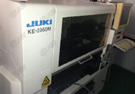
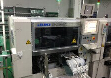
The placement machine:
There are many varieties of current placement machines, but whether it is a fully automatic high-speed placement machine or a manual low-speed placement machine, its overall layout has similarities.The automatic placement machine is a computer-controlled high-precision automation device that integrates the electrical machine of the collecting machine. It is mainly composed of a rack, a PCB conveying and bearing organization, a drive system, a positioning and alignment system, a placement head, a feeder, and an optical system. The recognition system, sensor and computer control system are composed of the functions of capture-displacement-positioning-placement, etc., and SMD components are quickly and accurately mounted.
frame:
The rack is the base of the machine, and all the transmission, positioning organization and feeder are firmly fixed on it, so it is necessary to have the mechanical strength and rigidity to meet. The current placement machine has various types of racks, including all casting type and steel plate welding type.The first is of all-roundness, good rigidity, small deformation, stable operation, and is usually applied to advanced machines; the second is characterized by simple processing and relatively low cost. The rack in which the machine is selected in detail depends on the overall depiction and load-bearing of the machine, and the operation process should be smooth, easy, and free of vibration.