| Service Hotline: | 0755-25566186 |
| 130-6691-6396 |
| Service Hotline: | 0755-25566186 |
| 130-6691-6396 |

Shenzhen Juke Industry Co., Ltd.
Tel: (86) 755-25566186
Fax: (86) 755-29668058
E-mail:jakizhu@163.com
Contact:
Zhu Wenwu
Mobile: 13928444330
QQ: 504060299
Zhu Ganghui
Mobile: 13714798680
QQ: 1046243838
Miss Zhou
Mobile: 13066916396
QQ: 1253838927
Address:1006 Huamei Building, Huamei Road, Songgang, Bao'an District. Shenzhen
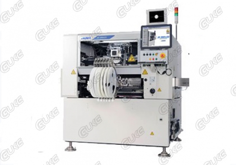
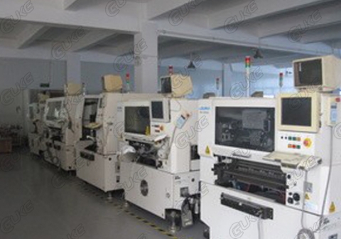
The placement machine is able to stably, quickly, completely, and correctly draw the device without causing any damage to the device and the base plate, and quickly and accurately mounts the device in a specified position. Currently, the device has been widely used in military industry, home appliances, etc. Communication, computer and other industries. SMT equipment mainly considers its mounting accuracy and mounting speed during the purchase. In actual use, in order to effectively improve product quality, reduce the cost of production and improve production efficiency, how to improve and maintain the SMT equipment placement rate is The most important topic before users.
According to the placement machine from the placement of the entire process, from a simple point of view of the equipment, the correct setting of the nozzle pickup height, take the position of the suction nozzle center and the relative position of the feeder, affect the device placement rate The main factor is in the location of the pick-up. According to the statistical information of production equipment, the impact of the equipment accounts for more than 80% of the total influencing factors. The causes are:
On the one hand, the feeder on the device storage and transportation device and the suction nozzle on the other hand, about 60% of the feeders in the film, about 40% due to the nozzle pollution.
Second, the feeder effect
The influence of the feeder is concentrated on the feeding exception. The feeder can be driven by several types such as motor drive, mechanical drive, and cylinder drive. Here, take the mechanical drive as an example to illustrate the effect of the feeder on the placement rate:
1: The drive part wears
The mechanical driving mechanism drives the feeding mechanism by the cam spindle, quickly knocks the search arm of the feeder, and makes the connected ratchet wheel drive the component braid to move forward by a connecting rod, and simultaneously drives the plastic tape reel to be edited. With the plastic cap on the belt away, the nozzle drops to complete the take-out action. However, due to the high-speed access to the feeder by the feeding mechanism, after a long period of use, the pawl of the feeder wears badly, causing the pawl to be unable to drive the plastic tape of the take-up reel to be normally peeled, so that the picking nozzle cannot complete the picking work. Therefore, the feeder should be carefully checked before installing the taping. The worn feeders of the ratchet wheel should be repaired immediately, and those that cannot be repaired should be promptly replaced.
2: Distortion of feeder structure
Because of long-term use or improper operation of the operator, the belt cover, thimble, springs and other movement mechanisms produce deformation, corrosion, etc., resulting in device bias, vertical film or inability to device, so it should be regularly checked and found problems in time Handling, in order to avoid causing a lot of device waste, while installing the feeder should be correctly and firmly installed on the supply section platform, in particular, no feeder height detection equipment, otherwise it may cause the feeder or equipment damage.
3: poor lubrication of the feeder
Generally, the maintenance and maintenance of feeders are easily overlooked, but regular cleaning, cleaning and refueling are essential tasks.
Third, the suction nozzle
The suction nozzle is also another important factor affecting the placement rate. There are internal and external causes.
1: Internal cause
On the one hand, the vacuum negative pressure is insufficient, and the mechanical valve on the placement head is automatically converted before the suction nozzle takes the part. It is converted from blowing gas to true. It absorbs and generates a certain negative pressure. When the suction part is taken, the negative pressure sensor detects the value at a certain value. In the range, the machine is normal, and vice versa. Generally, the negative pressure at the pickup position to the mounting position suction nozzle should be at least above 400mmHg. When the mounting large device negative pressure should be above 70mmHg, the filter in the vacuum pump should be cleaned periodically to ensure sufficient negative pressure; At the same time, the working status of the negative pressure detection sensor should be checked regularly. On the other hand, the filter on the placement head and the filter on the suction nozzle are blackened due to the contamination of the surrounding environment or the impure air source. Therefore, the filter should be replaced regularly. Generally, the filter on the suction nozzle should be replaced at least once every two months. The filter on the mounting head should be replaced at least once every six months to ensure smooth airflow.
2: external reasons
On the one hand, the pressure of the gas source circuit is depressurized, such as the aging and cracking of the rubber tube, the aging and wear of the seal, the wear of the nozzle after long use, and the other reason is due to the adhesive or dust in the external environment, especially the paper tape packaging. The large amount of waste generated after the components are cut off causes the suction nozzle to be blocked. Therefore, due to the degree of cleanliness of the suction nozzle being checked daily, the pick-up condition of the suction nozzle is monitored at any time. The suction nozzle that is jammed or has bad pick-up time should be promptly cleaned. Or replace it to ensure a good condition. At the same time when installing the suction nozzle, it must be ensured that it is properly and firmly installed, otherwise it will cause damage to the suction nozzle or the equipment.
Four: device detection system
The device inspection system is a necessary guarantee for placement accuracy and placement accuracy.Divided into device light identification system and device pose detection.
1: The optical identification system is an optical camera system fixedly installed, which is optically imaged by the camera to identify the outline of the components during the rotation of the placement head, and measures and records the center position and rotation angle of the device relative to the camera. It is passed to the transmission control system for compensation of XY coordinate position deviation and θ angle deviation. The advantages are accuracy and flexibility applicable to various shapes and shapes of devices. It has a reflection recognition method based on the device electrode as the identification basis, the recognition accuracy is not affected by the size of the nozzle, generally SOP, QFP, BGA, PLCC and other devices use the reflection recognition method. The transmission recognition method is based on the appearance of the component, and the recognition accuracy is affected by the size of the nozzle. When the nozzle shape is larger than the device outline, the outline of the nozzle is identified in the image.
As the light source of the optical camera system is used after a period of time, the light intensity will gradually decrease. Because the light intensity is proportional to the gray value of the solid-state image conversion, the larger the gray value, the clearer the digital image. Therefore, as the light source light intensity decreases, the gray value also decreases, but the gray value stored in the machine will not automatically decrease with the light source light intensity decreases, then when the gray value is lower than a certain At the time of value, the image cannot be identified, so the calibration test must be performed regularly. 1 Re-display 2 Adjust the aperture focal length. The gray value is directly proportional to the light intensity of the light source. When the light intensity of the light source is weak enough to identify the device, the light source must be replaced. At the same time, the lens, glass plate, and dust and components on the reflective plate should be cleaned regularly to prevent the light source from being affected by dust or components, resulting in poor recognition; In addition, you must also correctly set the camera's initial data.
2: The whole attitude detection is through the linear sensor installed on the frame, high-speed scanning from the lateral direction of the device to detect the device's suction state, and accurately detect the thickness of the device, when the thickness and the measured value set in the part library When the allowable error range is exceeded, there is a defect in thickness detection, resulting in loss of parts.Therefore, it is very important to correctly set the data of the device in the part library and the reference data for thickness detection and control, and the thickness of the device must be frequently measured repeatedly. At the same time, the linear sensor should be cleaned regularly to prevent the adhesion of dust, debris, oil, and other components on the attached surface.
Fifth, bad device braiding
The accuracy of device placement is the result of a combination of multiple factors. In addition to the reasons for the device itself, bad tape braiding also has a great impact on it, which is mainly manifested in:
A: The error of the pitch of the perforation is large.
B: The shape of the device is not good.
C: The braided square hole has an irregular shape or is too large, causing the device to be caught or turned laterally.
D: The adhesive force of the tape and the plastic hot pressing tape is too large to be peeled off normally, or the device is stuck on the bottom tape.
E: Grease on the bottom of the device.
Six: Basic Management
How to make good use of high-quality equipment to create maximum profits is the goal pursued by the company. How can we achieve our goals and rely mainly on scientific management methods:
A: Establish a regular employee training system to improve the quality of employees.
People are the soul of the enterprise and the fundamental part of the enterprise's entrepreneurship and development. Therefore, we must pay attention to the skills training of employees and the training of ideas. We should be able to operate the equipment correctly and correctly, correctly install and use the feeders, and regularly maintain and maintain the equipment so as to effectively ensure product quality, reduce material consumption, and increase production efficiency. .
B: Establish a regular equipment maintenance plan.
Advance TPM management, implement preventive maintenance and overhaul, thereby reducing equipment downtime due to temporary faults and pursuing maximum equipment utilization efficiency.
C: Sound equipment maintenance files.
1: Maintenance records. Record the phenomenon of failure, analysis process, processing situation, replacement of spare parts, etc.
2: Spare part replacement record. Analyze the reasons for the replacement of spare parts, spare parts replacement cycle, reduce the backlog of spare parts funds, and reduce production costs.
D: Sound equipment operation file.
1: The device running status timely login table.
2: Equipment operation status list.
3: Running status monitoring chart.
4: maintenance workers on duty equipment operation status monitoring diagram.
5: Monthly list of equipment operating conditions.
6: Equipment monthly operating status summary table.
Seven: SMT machine failure
1: When a fault occurs, it is recommended to solve the problem as follows:
A: Detailed analysis of the working order of the equipment and the logical relationship between them.
B: Understand the location, link and degree of failure, and whether there is abnormal sound.
C: Understand the operation process before the failure.
D: Whether it occurs on a specific head or nozzle.
E: Whether it occurs on a specific device.
F: Whether it occurs on a specific lot.
G: Whether it happened at a specific moment.
2: Analysis of common faults.
A: component placement offset
Mainly refers to component placement on the PCB, offset in the XY position
B: device placement angle offset
Mainly refers to the angular rotation of the device when it is mounted
C: Component loss:
Mainly refers to the loss of components between the suction position and the patch position
D: The pickup is abnormal:
E: Randomness does not patch
Mainly refers to the nozzle is not mounted at the low position of the patch
F: bad pickup attitude:
Mainly refers to the situation of vertical film, oblique film, etc.